
If 'KORG USB-MIDI Device' is shown rather than 'KORG Grandstage', open the Properties dialog and click Uninstall in the Driver tab. Then check 'Delete the driver software' and click OK. This download record installs USB Type C Power Delivery Controller for Intel® NUC11TN. Driver: Windows 10, 64-bit. 1.0.9.5 Latest: 1/10/2021: Intel® Ethernet (LAN) Network Connection Driver for Intel® NUC11TN. This download record installs Intel® Ethernet (LAN) Network Connection Driver for Intel® NUC11TN. Driver: Windows 10, 64-bit. 1.0.2. All current software, firmware, and drivers for the Surface Pro 3; including optional WinTab drivers. Links to drivers for other Surface devices are in the Details section below. Usb Endoscope Camera Driver free download - Chicony USB 2.0 Camera, USB Audio ASIO Driver, VIA USB 2.0 Host Controller Driver, and many more programs.
Contents
- 2 Reference Hardware
- 3 Reference Firmware
- 5 The USB Generic HID C# Class Library
- 5.1 Using the class-library
If you’ve dabbled with PIC18F microcontrollers and the USB Generic HID standard before (perhaps you’ve even tried my Building a PIC18F USB device project) then you will have noticed that there is a lot of complexity in supporting USB on both the PIC18F and the Windows host-side of things.
Getting beyond the basic steps of reading a switch and flashing an LED (how many projects have you built to flash LEDs?!) is actually quite a large task with a steep learning-curve.
To make things easier on the hobbyist who wishes to delve into more exciting projects, I’ve developed a framework for producing USB devices which covers both the Windows host-side application development and the PIC18F firmware itself. The framework consists of a Visual Studio C# class library (which handles all of the intricacy of dealing with the Windows specific SDKs and operating system requirements), a windows reference application (which demonstrates how to use the class library and acts as a testing front-end for the library), a simple USB hardware reference design and (last but not least!) a PIC18F4550 firmware which communicates with the class library.
In essence this means that you can rapidly develop and test a USB device and the Windows host-application with a minimum of USB Generic HID protocol knowledge. The class library gives you a very simple interface to the USB device from C# and the firmware serves as an example of how to create the specific software needed on the PIC for your device design.
The framework includes the ability to pass commands and responses to and from the USB device as well as bi-directional bulk-transfer of data allowing you to build more complex data-capture applications which require more information to be passed quickly from host to device and vice-versa.
In this article I will go over each element of the framework and show how you can use it to develop your own creative USB devices.
For the impatient, here is a quick YouTube video of the framework in action. The LCD driver example shown in the video can be downloaded below:
Version 3 of the USB library and firmware is now available (2011-10-16). I’ve made several major and minor enhancements to the library as well as some bug fixing. Here is a list of the enhancements and changes:
- Firmware
- Firmware is now targeted for the Microchip C18 compiler (and is no longer compatible with Hi-Tech PICC18)
- Microchip’s Application Library (containing the USB stack) is now separated from the framework code and is installed standalone
- The firmware now supports version 2.9a of the USB stack
- Support for USB bootloaders is now included (lightly tested at the moment)
- Both interrupt driven USB polling and non-interrupt driven USB polling are now supported
- Debug stream now supports dynamic text so you can place live variables and other information into the in-built debug functions
- Open-source firmware code now separated correctly from Microchip stack code
- General code clean-up with better (and more concise) comments and notes
- Host Reference Application
- Fixed memory leakage issue in non-Managed code (readRawReportFromDevice method)
- Changed the method used for registering to receive device event notifications. This is now handled by the library and does not need a WndProc override in the user code
- General code clean-up
In addition I’ve also updated all of the circuit diagrams and included a new schematic for the PIC18F2550.
Please ensure that you specify which version of the USB framework you are using when asking for help in the comments.
The reference hardware is extremely simple and can be built on a breadboard if required. I’ve made the pin-out of the hardware identical to the PIC DEM FS USB board available from Microchip to allow you to buy a reference board (if you want to!), you can also use my clone of the Microchip board – the PIC USB Development Board. If you don’t have the time/money/inclination to make a reference board here is a circuit schematic of the minimum required hardware for the reference board for both the PIC18F4550 and PIC18F2550 microcontrollers:
PIC18F4550 Circuit Schematic
PIC18F2550 Circuit Schematic
Breadboard Layout
The next picture shows the reference hardware built on an experimenter’s breadboard (using the PIC18F4550):
The reference hardware provides 4 LEDs which are used to show the status of the USB device as it processes the various requests that can be sent to it from the Windows host-application. The 4 LEDs (from left-to-right) mean:
- Power is on – device is ready
- USB enumerated – device is ready to communicate
- Success indicator (this flashes as commands are correctly processed)
- Failure indicator (this flashes if a command was not correctly processed)
The board provides all you need to add in your own devices and circuity as you require, you can even remove the LEDs, the only part the firmware truly requires is the USB port and its associated hardware.
Self-Powered USB Devices
Visual Productions Usb Devices Driver Download Windows 10
The reference hardware shown above is for a bus-powered USB device (it takes its power directly from the host computer). This requires the fewest parts and gives you a very simple circuit, however the current draw of the device is limited to 100mA. If you want to build devices that consume more power (to drive more hardware such as relays, motors, arrays of LEDs, etc.) you will need to make the device self-powered.
The following circuit schematic shows a simple self-powered version of the reference board. A LM7805 5V regulator is added to regulate the DC input. The 5V input from the USB bus is directed to RA0 on the PIC18F4550 which allows the firmware to detect when the USB cable is connected and disconnected. You can omit this power-sense feature, however that means that your firmware will need to constantly poll the USB stack to see if a cable is connected.
The reference firmware is based on Microchip’s USB stack version 2.9a. The firmware provides both the USB stack and a simple structure for building PIC18F USB HID firmware around. The firmware provided performs a number of tests (along with the Windows C# application) which allow quick verification that the firmware and application libraries are functioning correctly.
In the firmware you will find (located in the main.c source file) an implementation for several commands that are mirrored in the reference application:
- 0x80: Single packet write to device – This command receives a single command and data packet from the host (which is 64 bytes long), the packet should contain the command byte (in the first byte of the packet) and then the numbers 1-63 in the remaining bytes. This allows the firmware to confirm that the whole packet was received correctly.
- 0x81: Single packet read/write – This is similar to 0x80, however the firmware generates a return packet (filled with similar data) and passes it back to the host
- 0x82: Single packet write, 128 packet read – This command receives a single packet from the host and, in return, sends back 128 64 byte packets containing data. This command simulates the requirements of bulk data transfer from the device to the host (for applications like data-capture, etc.)
- 0x83: 128 packets write, single packet read – This command receives a command from the host followed by 128 64 byte packets containing data. This is basically the opposite of 0x82 where the host is bulk transferring data to the USB device (used in applications like display drivers, etc.)
- 0x84: Single packet write, time-out on read – This command is a little different from the others. It’s used to simulate a failure scenario on the host-side where a command is sent and the host expects a reply, but the firmware does not reply (simulating a bug in the firmware). This really doesn’t do much on the PIC device side, but it is useful for testing what the host-application does when the event occurs.
Not only does the reference firmware provide a test environment for the host class library, but it also serves as an example of how to communicate bi-directionally with the host for both simple command and response as well as bulk data transfer.
The reference firmware is GPL’d open-source, so you are free to use it and adapt it to your requirements. Also if you have any suggestions for improvement I’d love to hear from you in the comments.
Installing and compiling the reference firmware
The reference firmware is targeted for the Microchip C18 compiler (and will not work with other PIC compilers without alteration). The firmware also relies on the Microchip USB stack (which is linked in enabling the code to be easily updated as new versions of the stack are release).
To install the firmware you will need to create a directory in which to place both the library and the firmware. You then have to run the Microchip Application Library installer and instruct it to install into a directory called “Microchip Solutions v2011-07-14” under the directory you created in the last step. The firmware is only tested against version 2.9a of the stack (which is contained in the v2011-07-14 installer) and you can download the library installer [http://ww1.microchip.com/downloads/en/softwarelibrary/microchip-application-libraries-v2011-07-14-windows-installer.exe here].
Next grab a copy of the firmware zip file (at the bottom of this article) and unzip it with the application library. If all goes well you should now have two sub-directories in the same directory called “Microchip Solutions v2011-07-14” and “USB_GenericHID_Firmware_3_0_0_0”. Now double-click on the “USB_GenericHID_Firmware_3_0_0_0” directory and load the project file USB_GenericHID_Firmware_3_0_0_0.mcp.
If you alter the relative location of either the library or the firmware you will need to change the include path in the firmware project to tell MPLAB where to find the application library. You can do this in MPLAB by going Project -> Build Options Project -> Directories -> Include search path and changing the relative path to match your set-up.
The reference application uses the C# class library to communicate with the reference firmware. It provides a simple interface to the 5 commands available allowing you to select which command you would like to send. The application also creates the commands and data to send to the device as well as interpreting the data and responses sent back by the firmware to confirm that everything worked as it should.
Here you can see the GUI interface from the reference application running on a computer with Windows 7:
The 5 tests correspond to the 5 commands provided by the firmware. When you click on a test button the command is sent to the firmware and both the firmware (through the success and failure LEDs) and the host (providing a ‘test passed’ or ‘test failed’ message) provides feedback on the success of the test.
Furthermore, the C# class library provides USB device ‘events’ to the application letting it know when the USB device is attached and detached from the host. This is tested by removing and plugging in the USB connector whilst watching the status bar at the bottom of the window. If all is well you should see ‘device attached’ and ‘device detached’ messages. Also, the application disables (greys-out) the test buttons when no device is found.
The underlying C# USB generic HID class-library provides a base-class on which to build applications. The reference application defines a class for its own ‘specialised’ USB device which then inherits all of the accessible functions from the base-class. The application then extends the base-class to include its own methods for communicating with the device. Simply put, the specialised class has to provide an interface from the commands the device must support (0x80, 0x81, etc.) to the ‘raw’ send and receive methods provided by the class library.
This allows you to be very flexible in how you communicate with the firmware since you are free to define your own commands in any way you like.
Whenever changes, bug-fixed or modifications are performed on the USB generic HID class-library you can use the reference firmware and application to test to ensure that the library is still functioning correctly, this saves a lot of time later on when unforeseen issues pop up (as they always do!).
There are two ways to approach the class-library namely “How do I use it?” and “How does it work?”.
If you are interested in the inner workings of the class library I suggest you load it up into Visual Studio and take a look at the code. I’ve tried to structure it as clearly as possible and also comment it well. Most of the complexity is borrowed, adapted and (in certain cases!) written from scratch. By making the class-library specific to the issues of Generic HID communication with microcontrollers I’ve managed to remove a lot of the complexity of writing truly generic drivers.
There is also a lot of built-in debugging information. If you compile the reference application in Visual Studio’s ‘debug’ mode you will see a complete log of the application (and class-library’s) activities once you exit the application.
Using the class-library
Once you’ve included the class library in your project (for an example of how to do this simply take a look at the reference application project files which are included below), you will need to add in some lines of C# code to your main form to get the class-library up and running.
First up is the code which needs to go into the class constructor of your main form (usually called Form1()): Softhard 1394 driver download for windows 10 free.
This code does 3 things:
- Firstly it initiates the usbReferenceDevice class (which is a specialised form of the libraries base-class) and passes the VID and PID of the target device
- It adds a ‘listener’ function to the form which receives the events generated by the USB device (attach and detach events)
- Finally it performs a first-attempt at discovering the target USB device (the device might already be plugged in, so no notifications will be sent, even though the device is there)
Next up are two more items required by the class-library:
The first command generates an ‘instance’ of the usb device class which is used by the first code example to get the class up and running.
The second method is the USB event listener which is called by the class library when the USB device is detached or attached and allows the application to perform tasks such as updating the status bar and enabling/disabling form controls (this event driven method avoids the usual polling mechanisms most form-applications use to monitor the USB state and is far more efficient).
Once this is done you are free to add whichever windows, buttons and controls your application requires. The primary integration of the class library is deliberately as simple as possible. However to communicate with your USB device there is a little more work to be done.
To represent your own particular USB device you must generate a class which represents the device. This is as simple as adding a class to your project. The class must inherit the base library class and also define some methods to allow your application to communicate with the USB device. Don’t worry if this sounds complex, it really isn’t, and the reference application provides all the example code you need in the usbReferenceDevice.cs source file.
The first part of this class defines the class itself and creates it’s own ‘constructor’ to allow you to add in any initialisation your own device might need. The code looks like the following:
In the code example you can see the correct way of defining the class (using the class library as the base) and how to ‘pass-through’ the VID and PID from your constructor to the class library.
Once this is done you are free to add in whatever methods your device requires. Primarily, these will be methods which communicate to and from the device. In the reference application you have 5 example methods which use the four different communication commands supported by the reference firmware (as well as the 5th command which is purely for demonstrating how the class reacts to firmware bugs).
Here is an example method which sends a command to the USB device:
As you can see from the source it’s very simple, the class library takes care of all the details. You simply assemble the command and data you wish to send and call the write method, then all that’s left it to test the result to ensure it was successful.
There are very few ‘public’ methods that the class provides, but here is a list of them and what they are used for:

findTargetDevice()
This method searches for the USB device based on the VID and PID which was supplied when the object was created.
handleDeviceNotificationMessages()
This method deals with interpreting the windows notifications received by the application and seeing if they could relate to the USB device. If they do, then the method starts searching for the USB device, or registers it as detached dependent on the messages received.
onUsbEvent()
This method is part of the event mechanism used by the class-library to inform your application of the USB device being attached or detached.
readMultipleReportsFromDevice()
This method is used for incoming bulk data transfers, see the usbReferenceDevice.cs source file (in the reference application) for details of how this is used.
readSingleReportFromDevice()
This method is used to get a single report packet from the USB device. Again, usbReference.cs is the best place for an example of how it’s used.
registerForDeviceNotifications()
This method is used to instruct windows to send device notifications to your application (which are then picked up by handleDeviceNotificationMessages() for processing)
writeRawReportToDevice()
This method is used for sending commands and data to the USB device. Again, usbReference.cs is the best place for an example of how it’s used.
isDeviceAttached
This property can be tested to see if a USB device is present. It has a value of true if the device is attached and false if the device is detached.
The C# class-library and the reference application are both released under the GPL so you are free to use them and adapt them to your needs. I don’t pretend to be an expert in C# (!) so if you have any suggestions for improvements, or bug reports, let me know in the comments!
With a complete reference environment and test suite you have everything you need to create your own advanced USB projects. There is no end to the hardware you can interface to your PC using USB and PIC microcontrollers. Even if you’re not a great fan of the PIC, the class-library is generic to all microcontrollers which support Generic HID protocol communication.
As with all learning-experiences, start simple and slow and gradually dig deeper in to the way the class-library operates and how Windows applications are created in C#. There are endless possibilities for your next hack!
Currently the class-library doesn’t support more than one USB device with the same VID and PID as this makes the device selection process more difficult (for both the library and the application). I’ve included some pretty comprehensive device enumeration methods in the class, so adding in support should be straight-forward. I hope to support this soon in an updated version of the library.
Visual Studio 2010 C# project files and source for the Reference Application and the Generic HID USB class-library version 3_0_0_0:
The MPLAB PIC18F4550 firmware project and source files for Microchip C18:
The three schematic drawings featured in this article (in Eagle CAD format):
To demonstrate the flexibility of the framework I created a simple USB device which allow you to control an LCD display from Windows. The display is a simple HD44780 compatible 16×2 character display. Please see the PC Case USB LCD project page for more details.
Building a PIC18F USB device – Note: this is based on the old C++ library, I hope to update it soon
PC Case USB LCD – Note: this is based on the version 2 framework, I hope to update it soon

Open Source Visual C++ Class for USB Generic HID Communication – This project is obsolete, the C# library is the only version which is under current development.
-->In this topic you'll use the USB Kernel-Mode Driver template provided with Microsoft Visual Studio Professional 2019 to write a simple kernel-mode driver framework (KMDF)-based client driver. After building and installing the client driver, you'll view the client driver in Device Manager and view the driver output in a debugger.
For an explanation about the source code generated by the template, see Understanding the KMDF template code for a USB client driver.
Prerequisites
For developing, debugging, and installing a kernel-mode driver, you need two computers:
- A host computer running Windows 7 or a later version of the Windows operating system. The host computer is your development environment, where you write and debug your driver.
- A target computer running Windows Vista or a later version of Windows. The target computer has the kernel-mode driver that you want to debug.
Before you begin, make sure that you meet the following requirements:
Software requirements
- Your host computer hosts your development environment and has Visual Studio Professional 2019.
- Your host computer has the latest Windows Driver Kit (WDK) for Windows 8. The kit include headers, libraries, tools, documentation, and the debugging tools required to develop, build, and debug a KMDF driver. To get the latest version of the WDK, see Download the Windows Driver Kit (WDK).
- Your host computer has the latest version of debugging tools for Windows. You can get the latest version from the WDK or you can Download and Install Debugging Tools for Windows.
- Your target computer is running Windows Vista or a later version of Windows.
- Your host and target computers are configured for kernel debugging. For more information, see Setting Up a Network Connection in Visual Studio.
Hardware requirements
Get a USB device for which you will be writing the client driver. In most cases, you are provided with a USB device and its hardware specification. The specification describes device capabilities and the supported vendor commands. Use the specification to determine the functionality of the USB driver and the related design decisions.
If you are new to USB driver development, use the OSR USB FX2 learning kit to study USB samples included with the WDK. You can get the learning kit from OSR Online. It contains the USB FX2 device and all the required hardware specifications to implement a client driver.
You can also get a Microsoft USB Test Tool (MUTT) devices. MUTT hardware can be purchased from JJG Technologies. The device does not have installed firmware installed. To install firmware, download the MUTT software package from this Web site and run MUTTUtil.exe. For more information, see the documentation included with the package.
Recommended reading
- Developing Drivers with Windows Driver Foundation, written by Penny Orwick and Guy Smith. For more information, see Developing Drivers with WDF.
Instructions
Microsoft Usb Video Device Driver Windows 10
Step 1: Generate the KMDF driver code by using the Visual Studio Professional 2019 USB driver template
For instructions about generating KMDF driver code, see the steps in Writing a KMDF driver based on a template.
For USB-specific code, select the following options in Visual Studio Professional 2019
- In the New Project dialog box, in the search box at the top, type USB.
- In the middle pane, select Kernel Mode Driver, USB (KMDF).
- Select Next.
- Enter a project name, choose a save location, and select Create.
The following screen shots show the New Project dialog box for the USB Kernel-Mode Driver template.
This topic assumes that the name of the Visual Studio project is 'MyUSBDriver_'. It contains the following files:
Download A Driver For Usb
| Files | Description |
|---|---|
| Public.h | Provides common declarations shared by the client driver and user applications that communicate with the USB device. |
| <Project name>.inf | Contains information required to install the client driver on the target computer. |
| Trace.h | Declares tracing functions and macros. |
| Driver.h; Driver.c | Declares and defines driver entry points and event callback routines. |
| Device.h; Device.c | Declares and defines event callback routine for the prepare-hardware event. |
| Queue.h; Queue.c | Declares and defines an event callback routine for the event raised by the framework's queue object. |
Step 2: Modify the INF file to add information about your device

Before you build the driver, you must modify the template INF file with information about your device, specifically the hardware ID string.
In Solution Explorer, under Driver Files, double-click the INF file.
In the INF file you can provide information such as the manufacturer and provider name, the device setup class, and so on. One piece of information that you must provide is the hardware identifier of your device.
To provide the hardware ID string:
Attach your USB device to your host computer and let Windows enumerate the device.
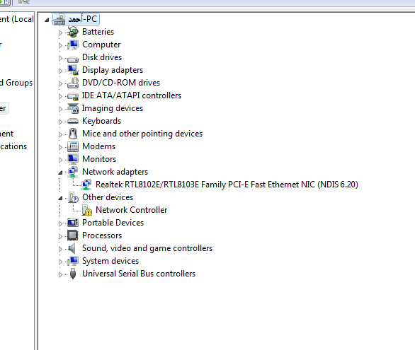
Open Device Manager and open properties for your device.
On the Details tab, select Hardward Ids under Property.
The hardware ID for the device is displayed in the list box. Select and hold (or right-click) and copy the hardware ID string.
Replace USBVID_vvvv&PID_pppp in the following line with your hardware ID string.
[Standard.NT$ARCH$] %MyUSBDriver_.DeviceDesc%=MyUSBDriver__Device, USBVID_vvvv&PID_pppp
Step 3: Build the USB client driver code
To build your driver
- Open the driver project or solution in Visual Studio Professional 2019
- Select and hold (or right-click) the solution in the Solution Explorer and select Configuration Manager.
- From the Configuration Manager, select the Active Solution Configuration (for example, Windows 8 Debug or Windows 8 Release) and the Active Solution Platform (for example, Win32) that correspond to the type of build you're interested in.
- From the Build menu, select Build Solution.
For more information, see Building a Driver.
Step 4: Configure a computer for testing and debugging
To test and debug a driver, you run the debugger on the host computer and the driver on the target computer. So far, you have used Visual Studio on the host computer to build a driver. Next you need to configure a target computer. To configure a target computer, follow the instructions in Provision a computer for driver deployment and testing.
Step 5: Enable tracing for kernel debugging
The template code contains several trace messages (TraceEvents) that can help you track function calls. All functions in the source code contain trace messages that mark the entry and exit of a routine. For errors, the trace message contains the error code and a meaningful string. Because WPP tracing is enabled for your driver project, the PDB symbol file created during the build process contains trace message formatting instructions. If you configure the host and target computers for WPP tracing, your driver can send trace messages to a file or the debugger.
Download Usb Device To Computer
To configure your host computer for WPP tracing
Create trace message format (TMF) files by extracting trace message formatting instructions from the PDB symbol file.
You can use Tracepdb.exe to create TMF files. The tool is located in the <install folder>Windows Kits8.0bin<architecture> folder of the WDK. The following command creates TMF files for the driver project.
tracepdb -f [PDBFiles] -p [TMFDirectory]
The -f option specifies the location and the name of the PDB symbol file. The -p option specifies the location for the TMF files that are created by Tracepdb. For more information, see Tracepdb Commands.
At the specified location you'll see three files (one per .c file in the project). They are given GUID file names.
In the debugger, type the following commands:
.load Wmitrace
Loads the Wmitrace.dll extension.
.chain
Verify that the debugger extension is loaded.
Syntek drivers. !wmitrace.searchpath +<TMF file location>
Add the location of the TMF files to the debugger extension's search path.
The output resembles this:
Trace Format search path is: 'C:Program Files (x86)Microsoft Visual Studio 14.0Common7IDE;c:driverstmf'
To configure your target computer for WPP tracing
Make sure you have the Tracelog tool on your target computer. The tool is located in the <install_folder>Windows Kits8.0Tools<arch> folder of the WDK. For more information, see Tracelog Command Syntax.
Open a Command Window and run as administrator.
Type the following command:
tracelog -start MyTrace -guid #c918ee71-68c7-4140-8f7d-c907abbcb05d -flag 0xFFFF -level 7-rt -kd
The command starts a trace session named MyTrace.
The guid argument specifies the GUID of the trace provider, which is the client driver. You can get the GUID from Trace.h in the Visual Studio Professional 2019 project. As another option, you can type the following command and specify the GUID in a .guid file. The file contains the GUID in hyphen format:
tracelog -start MyTrace -guid c:driversProvider.guid -flag 0xFFFF -level 7-rt -kd
You can stop the trace session by typing the following command:
tracelog -stop MyTrace
Step 6: Deploy the driver on the target computer
- In the Solution Explorer window, select and hold (or right-click) the <project name>Package , and choose Properties.
- In the left pane, navigate to Configuration Properties > Driver Install > Deployment.
- Check Enable deployment, and check Import into driver store.
- For Remote Computer Name, specify the name of the target computer.
- Select Install and Verify.
- Select Ok.
- On the Debug menu, choose Start Debugging, or press F5 on the keyboard.
Note Do not specify the hardware ID of your device under Hardware ID Driver Update. The hardware ID must be specified only in your driver's information (INF) file.
For more information about deploying the driver to the target system in Visual Studio Professional 2019, see Deploying a Driver to a Test Computer.
You can also manually install the driver on the target computer by using Device Manager. If you want to install the driver from a command prompt, these utilities are available:
This tool comes with the Windows. It is in WindowsSystem32. You can use this utility to add the driver to the driver store.
For more information, see PnPUtil Examples.
This tool comes with the WDK. You can use it to install and update drivers.
Step 7: View the driver in Device Manager
Enter the following command to open Device Manager:
devmgmt
Verify that Device Manager shows a node for the following node:
Samples
MyUSBDriver_Device
Step 8: View the output in the debugger
Visual Studio first displays progress in the Output window. Then it opens the Debugger Immediate Window. Verify that trace messages appear in the debugger on the host computer. The output should look like this, where 'MyUSBDriver_' is the name of the driver module:
Related topics
Understanding the KMDF template code for a USB client driver
Getting started with USB client driver development